Business field 01
Heating elements built to your specification
Three constructions, one approach: we lay out the heating structure for your application — geometry, area power density, temperature distribution, termination — and manufacture from sample to series.
Heating foils
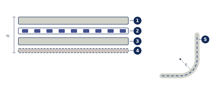
Flexible, thin heating elements: an etched resistive track laminated between two carrier films.
The heat is generated in an etched metal track, typically copper or a resistance alloy. Track width and spacing can be varied deliberately across the area — so power goes where it is needed rather than being spread evenly over the whole surface.
Depending on the temperature range the carrier is polyimide, PET or silicone. The small thickness and low thermal mass give short heat-up times; the foil follows curved surfaces and is usually bonded directly in place.
Construction and options
| Parameter | Value |
|---|---|
| Carrier material | Polyimide (PI), PET or silicone |
| Termination | Flying leads, ribbon cable or FFC/ZIF |
| Integrated temperature sensor | optional: NTC, PT1000 or thermal cut-out |
Customisable to your requirements
- Outline and cut-outs to your drawing
- Track layout for a deliberate temperature distribution or several separately driven heating zones
- Area power density and resistance dimensioned for your supply voltage
- Self-adhesive backing (PSA) or uncoated for bonding
- Integrated temperature sensor (NTC/PT1000) and thermal cut-out
- Termination position, cable length and connector
- Marking, printing and batch traceability
Typical applications
- Anti-condensation and de-icing on sensors and optics
- Temperature control in medical and laboratory equipment
- Battery pre-heating
- Displays and cameras at low ambient temperatures
- Heated measuring cells and sample chambers
PCB heating plates
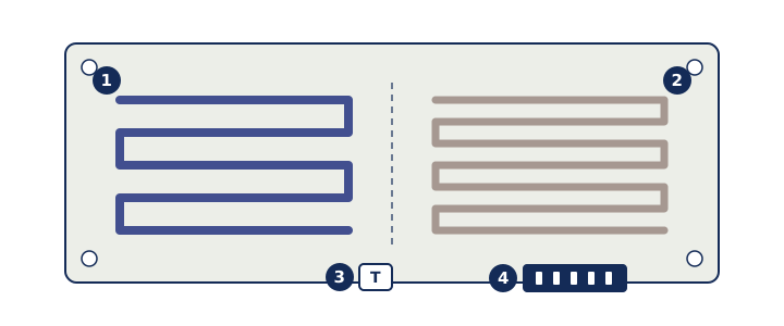
The heating structure as a resistive layer in the PCB stack-up — rigid, dimensionally accurate and combinable with sensing and control on the same board.
Instead of mounting a heater onto an assembly, it becomes part of it: the resistive track is a structured layer within the stack-up. Layer thickness and track geometry set the resistance; the layout sets the temperature distribution.
Copper is the default, but not the only option. Because its resistivity is very low, a copper track needs considerable length and a small cross-section to reach a given resistance. Where a higher sheet resistance is required — at higher operating voltage, or on a small heating area — we embed higher-resistance materials into the stack-up instead. The same resistance can then be realised on a considerably smaller area.
The base material is FR4, or an aluminium core (IMS) where higher power density and faster heat spreading are needed. Temperature sensors, control, power switching and the interface can be populated on the same board — saving wiring, contact resistances and tolerances.
Construction and options
| Parameter | Value |
|---|---|
| Base material | FR4, aluminium core (IMS) or ceramic |
| Resistive material | copper (standard) or higher-resistance materials for greater sheet resistance |
| Surface finish | ENIG, immersion tin or HASL |
| Integrated sensing | optional NTC/PT1000 populated, control on the same board |
Customisable to your requirements
- Outline, drill pattern and mounting points to your drawing
- Several separately controllable heating zones
- Copper layout for a defined temperature profile rather than a uniform surface
- Control electronics, power stage and interface on the same board
- Temperature sensors populated at measuring points you define
- Base material chosen for your temperature and power requirement
- Resistive material: copper or higher-resistance alternatives, matched to operating voltage and available heating area
- Series production with electrical end-of-line test and report
Typical applications
- Thermostatting of sensors and reference elements
- Heated measuring and sample cells
- Laboratory hotplates and incubators
- Process heat in benchtop and small appliances
- Condensation protection in enclosures and optics
Self-regulating heating plates
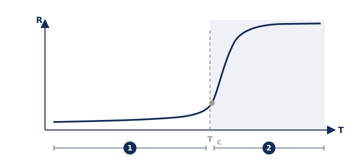
PTC heating elements that limit their own power: above the Curie temperature the resistance rises steeply and the absorbed power drops — with no control electronics at all.
The material is a positive-temperature-coefficient (PTC) ceramic: its resistance stays low up to the Curie temperature and rises by orders of magnitude above it. Such an element draws high power at switch-on, heats up quickly and then settles by itself at its regulating temperature.
Two practical properties follow. First, the heater cannot, by its operating principle, rise appreciably above the Curie temperature — even with blocked heat dissipation, a broken sensor lead or failed electronics. Second, it adapts to the load by itself: strong cooling makes it draw more power, weak cooling less.
Construction and options
| Parameter | Value |
|---|---|
| Operating principle | PTC ceramic, self-limiting above the Curie temperature |
| Temperature limiting | inherent to the material; no control electronics and no temperature sensor required |
| Over-temperature protection | inherent in the principle; optional additional cut-out for safety-critical installations |
| Termination | Flying leads, blade terminals or spring contacts |
Customisable to your requirements
- Regulating temperature set through the material's Curie point
- Area, outline and heat spreader to suit the installation
- Voltage level: low voltage or mains
- Thermal coupling: bonded, screwed or spring-loaded
- Termination method and cable exit position
- Additional thermal cut-out for safety-critical installations
Typical applications
- Pre-heating of batteries at low temperatures
- Condensation protection on outdoor cameras and sensors
- Frost protection in small and outdoor equipment
- Heating in hard-to-reach places without a sensor lead
- Applications where over-temperature must be ruled out
Related fields
From requirement to series
-
Specification
We clarify the application, constraints and acceptance criteria: temperature range, power, measuring range, installation, quantities, service life.
-
Design and samples
Design, engineering and sampled prototypes — each with a measurement report, so deviation from spec is documented rather than asserted.
-
Verification
Functional and endurance testing, thermal characterisation, EMC preparation and support through testing up to release.
-
Series
Manufacture of the components we developed, electrical end-of-line test, documentation, batch traceability and long-term availability.
Enquire about this field
Temperature range, power, measuring range, installation, quantity — with those we can answer concretely rather than generically.
Send an enquiry